Monday, September 16, 2013 Eric Richards

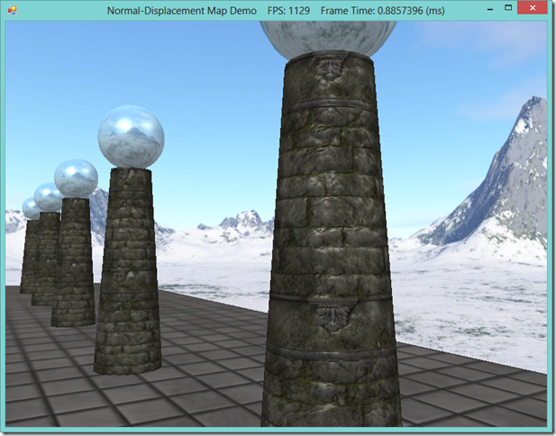
In our last example on normal mapping and displacement mapping, we made use of the new Direct3D 11 tessellation stages when implementing our displacement mapping effect.  For the purposes of the example, we did not examine too closely the concepts involved in making use of these new features, namely the Hull and Domain shaders.  These new shader types are sufficiently complicated that they deserve a separate treatment of their own, particularly since we will continue to make use of them for more complicated effects in the future.

The Hull and Domain shaders are covered in Chapter 13 of Frank Luna’s Introduction to 3D Game Programming with Direct3D 11.0 , which I had previously skipped over.  Rather than use the example from that chapter, I am going to use the shader effect we developed for our last example instead, so that we can dive into the details of how the hull and domain shaders work in the context of a useful example that we have some background with.

The primary motivation for using the tessellation stages is to offload work from the the CPU and main memory onto the GPU.  We have already looked at a couple of the benefits of this technique in our previous post, but some of the advantages of using the tessellation stages are:

  • We can use a lower detail mesh, and specify additional detail using less memory-intensive techniques, like the displacement mapping technique presented earlier, to produce the final, high-quality mesh that is displayed.
  • We can adjust the level of detail of a mesh on-the-fly, depending on the distance of the mesh from the camera or other criteria that we define.
  • We can perform expensive calculations, like collisions and physics calculations, on the simplified mesh stored in main memory, and still render the highly-detailed generated mesh.

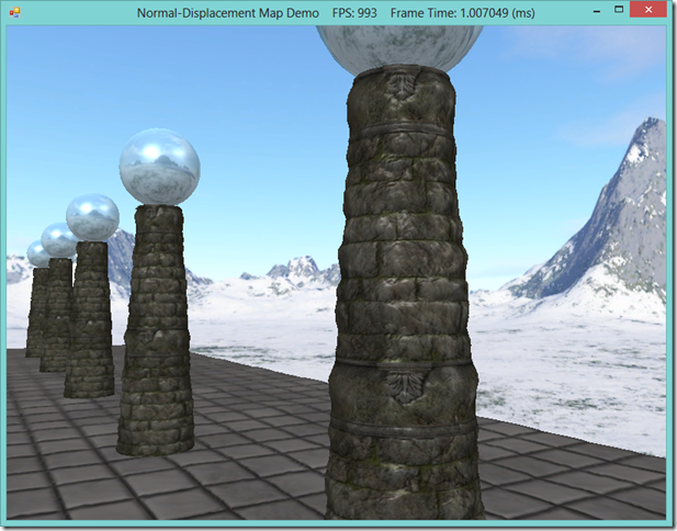
displacement-mapped


Monday, September 16, 2013 Eric Richards

Today, we are going to cover a couple of additional techniques that we can use to achieve more realistic lighting in our 3D scenes.  Going back to our first discussion of lighting, recall that thus far, we have been using per-pixel, Phong lighting.  This style of lighting was an improvement upon the earlier method of Gourad lighting, by interpolating the vertex normals over the resulting surface pixels, and calculating the color of an object per-pixel, rather than per-vertex.  Generally, the Phong model gives us good results, but it is limited, in that we can only specify the normals to be interpolated from at the vertices.  For objects that should appear smooth, this is sufficient to give realistic-looking lighting; for surfaces that have more uneven textures applied to them, the illusion can break down, since the specular highlights computed from the interpolated normals will not match up with the apparent topology of the surface.

image

In the screenshot above, you can see that the highlights on the nearest column are very smooth, and match the geometry of the cylinder.  However, the column has a texture applied that makes it appear to be constructed out of stone blocks, jointed with mortar.  In real life, such a material would have all kinds of nooks and crannies and deformities that would affect the way light hits the surface and create much more irregular highlights than in the image above.  Ideally, we would want to model those surface details in our scene, for the greatest realism.  This is the motivation for the techniques we are going to discuss today.

One technique to improve the lighting of textured objects is called bump or normal mapping.  Instead of just using the interpolated pixel normal, we will combine it with a normal sampled from a special texture, called a normal map, which allows us to match the per-pixel normal to the perceived surface texture, and achieve more believable lighting.

The other technique is called displacement mapping.  Similarly, we use an additional texture to specify the per-texel surface details, but this time, rather than a surface normal, the texture, called a displacement map or heightmap, stores an offset that indicates how much the texel sticks out or is sunken in from its base position.  We use this offset to modify the position of the vertices of an object along the vertex normal.  For best results, we can increase the tessellation of the mesh using a domain shader, so that the vertex resolution of our mesh is as great as the resolution of our heightmap.  Displacement mapping is often combined with normal mapping, for the highest level of realism.

normal-mapped displacement-mapped
The scene with normal mapping enabled.  Note the highlights are much less regular. The scene with displacement mapping enabled.  Note that the mesh geometry is much more detailed, and the sides of the column are no longer smooth.

This example is based off of Chapter 18 of Frank Luna’s Introduction to 3D Game Programming with Direct3D 11.0 .  You can download the full source for this example from my GitHub repository, athttps://github.com/ericrrichards/dx11.git, under the NormalDisplacementMaps project.

NOTE: You will need to have a DirectX 11 compatible video card in order to use the displacement mapping method presented here, as it makes use of the Domain and Hull shaders, which are new to DX 11.


Wednesday, September 11, 2013 Eric Richards

Last time, we looked at using cube maps to render a skybox around our 3D scenes, and also how to use that sky cubemap to render some environmental reflections onto our scene objects.  While this method of rendering reflections is relatively cheap, performance-wise and can give an additional touch of realism to background geometry, it has some serious limitations if you look at it too closely.  For one, none of our local scene geometry is captured in the sky cubemap, so, for instance, you can look at our reflective skull in the center and see the reflections of the distant mountains, which should be occluded by the surrounding columns.  This deficiency can be overlooked for minor details, or for surfaces with low reflectivity, but it really sticks out if you have a large, highly reflective surface.  Additionally, because we are using the same cubemap for all objects, the reflections at any object in our scene are not totally accurate, as our cubemap sampling technique does not differentiate on the position of the environment mapped object in the scene.

The solution to these issues is to render a cube map, at runtime, for each reflective object using Direct3D.  By rendering the cubemap for each object on the fly, we can incorporate all of the visible scene details, (characters, geometry, particle effects, etc) in the reflection, which looks much more realistic.  This is, of course, at the cost of the additional overhead involved in rendering these additional cubemaps each frame, as we have to effectively render the whole scene six times for each object that requires dynamic reflections.

This example is based on the second portion of Chapter 17 of Frank Luna’s Introduction to 3D Game Programming with Direct3D 11.0 , with the code ported to C# and SlimDX from the native C++ used in the original example.  You can download the full source for this example from my GitHub repository, at https://github.com/ericrrichards/dx11.git, under the DynamicCubeMap project.

image_thumb%25255B3%25255D[1]


Sunday, September 08, 2013 Eric Richards

This time, we are going to take a look at a special class of texture, the cube map, and a couple of the common applications for cube maps, skyboxes and environment-mapped reflections.  Skyboxes allow us to model far away details, like the sky or distant scenery, to create a sense that the world is more expansive than just our scene geometry, in an inexpensive way.  Environment-mapped reflections allow us to model reflections on surfaces that are irregular or curved, rather than on flat, planar surfaces as in our Mirror Demo.

The code for this example is adapted from the first part of Chapter 17 of Frank Luna’s Introduction to 3D Game Programming with Direct3D 11.0.   You can download the full source for this example from my GitHub repository, https://github.com/ericrrichards/dx11.git, under the CubeMap project.

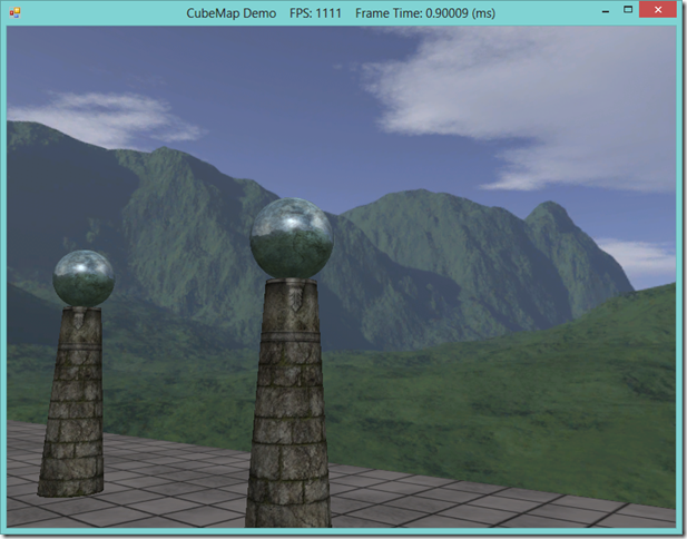
cubemap
Our skull & columns scene, with a skybox and environment-mapped reflections on the column tops

Sunday, September 08, 2013 Eric Richards

Hi everybody. This past week has been a rough one for me, as far as getting out any additional tutorials.  Between helping my future sister-in-law move into a place in Cambridge, a deep sea fishing trip, a year-long project at work finally coming to a critical stage, and the release of Rome Total War II, it's been hard for me to find the hours to hammer out an article. Not to fear, next week should see an explosion of new content, as I am way ahead on the coding side.  Expect articles on skyboxes and reflections using cube maps, normal and displacement mapping, terrain rendering with texture splatting and constant LOD, and loading meshes in commercial formats using Assimp.Net. Here are some teaser screenshots...

Using cube maps to render a skybox and reflections:

image

Real-time reflections using a dynamic cube map:

image

Normal and displacement mapping (click for full-size):

image image image
Flat lighting Normal mapped lighting Normal mapped lighting and displacement mapped geometry

Terrain rendering:

image image
  Wire-frame mode, note the far hills are made up of far fewer polygons than the nearer details.

Loading meshes with commercial file formats using Assimp.Net:

image