Sunday, November 03, 2013 Eric Richards

This weekend, I updated my home workstation from Windows 8 to Windows 8.1.  Just before doing this, I had done a bunch of work on my SSAO implementation, which I was intending to write up here once I got back from a visit home to do some deer hunting and help my parents get their firewood in.  When I got back, I fired up my machine, and loaded up VS to run the SSAO sample to grab some screenshots.  Immediately, my demo application crashed, while trying to create the DirectX 11 device.  I had done some work over the weekend to downgrade the vertex and pixel shaders in the example to SM4, so that they could run on my laptop, which has an older integrated Intel video card that only supports DX10.1.  I figured that I had borked something up in the process, so I tried running some of my other, simpler demos.  Same error message popped up; DXGI_ERROR_UNSUPPORTED.  Now, I am running a GTX 560 TI, so I know Direct3D 11 should be supported. 

However, I have been using Nvidia’s driver update tool to keep myself at the latest and greatest driver version, so I figured that perhaps the latest driver I downloaded had some bugs.  Go to Nvidia’s site, check for any updates.  Looks like I have the latest driver. Hmm…

So I turned again to google, trying to find some reason why I would suddenly be unable to create a DirectX device.  The fourth result I found was this: http://stackoverflow.com/questions/18082080/d3d11-create-device-debug-on-windows-8-1.  Apparently I need to download the Windows 8.1 SDK, now.  I’m guessing that, since I had VS installed prior to updating, I didn’t get the latest SDK installed, and the Windows 8 SDK, which I did have installed, wouldn’t cut it anymore, at least when trying to create a debug device.  So I went ahead and installed the 8.1 SDK from here.  Restart VS, rebuild the project in question, and now it runs perfectly.  Argh.  At least it’s working again; I just wish I didn’t have to waste an hour futzing around with it…


Monday, October 28, 2013 Eric Richards

Shadow mapping is a technique to cast shadows from arbitrary objects onto arbitrary 3D surfaces.  You may recall that we implemented planar shadows earlier using the stencil buffer.  Although this technique worked well for rendering shadows onto planar (flat) surfaces, this technique does not work well when we want to cast shadows onto curved or irregular surfaces, which renders it of relatively little use.  Shadow mapping gets around these limitations by rendering the scene from the perspective of a light and saving the depth information into a texture called a shadow map.  Then, when we are rendering our scene to the backbuffer, in the pixel shader, we determine the depth value of the pixel being rendered, relative to the light position, and compare it to a sampled value from the shadow map.  If the computed value is greater than the sampled value, then the pixel being rendered is not visible from the light, and so the pixel is in shadow, and we do not compute the diffuse and specular lighting for the pixel; otherwise, we render the pixel as normal.  Using a simple point sampling technique for shadow mapping results in very hard, aliased shadows: a pixel is either in shadow or lit; therefore, we will use a sampling technique known as percentage closer filtering (PCF), which uses a box filter to determine how shadowed the pixel is.  This allows us to render partially shadowed pixels, which results in softer shadow edges.

This example is based on the example from Chapter 21 of Frank Luna’s Introduction to 3D Game Programming with Direct3D 11.0 . The full source for this example can be downloaded from my GitHub repository at https://github.com/ericrrichards/dx11.git, under the ShadowDemos project.

image


Friday, October 25, 2013 Eric Richards

I had promised that we would move on to discussing shadows, using the shadow mapping technique.  However, when I got back into the code I had written for that example, I realized that I was really sick of handling all of the geometry for our stock columns & skull scene.  So I decided that, rather than manage all of the buffer creation and litter the example app with all of the buffer counts, offsets, materials and world transforms necessary to create our primitive meshes, I would take some time and extend the BasicModel class with some factory methods to create geometric models for us, and leverage the BasicModel class to encapsulate and manage all of that data.  This cleans up the example code considerably, so that next time when we do look at shadow mapping, there will be a lot less noise to deal with.

The heavy lifting for these methods is already done; our GeometryGenerator class already does the work of generating the vertex and index data for these geometric meshes.  All that we have left to do is massage that geometry into our BasicModel’s MeshGeometry structure, add a default material and textures, and create a Subset for the entire mesh.  As the material and textures are public, we can safely initialize the model with a default material and null textures, since we can apply a different material or apply diffuse or normal maps to the model after it is created.

The full source for this example can be downloaded from my GitHub repository, at https://github.com/ericrrichards/dx11.git, under the ShapeModels project.

image


Monday, October 21, 2013 Eric Richards

Particle systems are a technique commonly used to simulate chaotic phenomena, which are not easy to render using normal polygons.  Some common examples include fire, smoke, rain, snow, or sparks.  The particle system implementation that we are going to develop will be general enough to support many different effects; we will be using the GPU’s StreamOut stage to update our particle systems, which means that all of the physics calculations and logic to update the particles will reside in our shader code, so that by substituting different shaders, we can achieve different effects using our base particle system implementation.

The code for this example was adapted from Chapter 20 of Frank Luna’s Introduction to 3D Game Programming with Direct3D 11.0 , ported to C# and SlimDX.  The full source for the example can be found at my GitHub repository, at https://github.com/ericrrichards/dx11.git, under the ParticlesDemo project.

Below, you can see the results of adding two particles systems to our terrain demo.  At the center of the screen, we have a flame particle effect, along with a rain particle effect.

image


Tuesday, October 15, 2013 Eric Richards

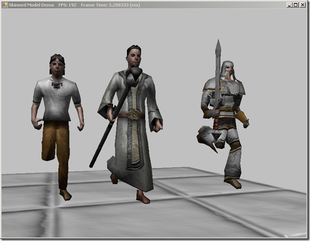
Sorry for the hiatus, I’ve been very busy with work and life the last couple weeks.  Today, we’re going to look at loading meshes with skeletal animations in DirectX 11, using SlimDX and Assimp.Net in C#.  This will probably be our most complicated example yet, so bear with me.  This example is inspired by Chapter 25 of Frank Luna’s Introduction to 3D Game Programming with Direct3D 11.0 , although with some heavy modifications.  Mr. Luna’s code uses a custom animation format, which I found less than totally useful; realistically, we would want to be able to load skinned meshes exported in one of the commonly used 3D modeling formats.  To facilitate this, we will again use the .NET port of the Assimp library, Assimp.Net.  The code I am using to load and interpret the animation and bone data is heavily based on Scott Lee’s Animation Importer code, ported to C#.  The full source for this example can be found on my GitHub repository, at https://github.com/ericrrichards/dx11.git under the SkinnedModels project.  The meshes used in the example are taken from the example code for Carl Granberg’s Programming an RTS Game with Direct3D .

Skeletal animation is the standard way to animate 3D character models.  Generally, a character model will be represented by two structures: the exterior vertex mesh, or skin, and a tree of control points specifying the joints or bones that make up the skeleton of the mesh.  Each vertex in the skin is associated with one or more bones, along with a weight that determines how much influence the bone should have on the final position of the skin vertex.  Each bone is represented by a transformation matrix specifying the translation, rotation and scale that determines the final position of the bone.  The bones are defined in a hierarchy, so that each bone’s transformation is specified relative to its parent bone.  Thus, given a standard bipedal skeleton, if we rotate the upper arm bone of the model, this rotation will propagate to the lower arm and hand bones of the model, analogously to how our actual joints and bones work.

Animations are defined by a series of keyframes, each of which specifies the transformation of each bone in the skeleton at a given time.  To get the appropriate transformation at a given time t, we linearly interpolate between the two closest keyframes.  Because of this, we will typically store the bone transformations in a decomposed form, specifying the translation, scale and rotation components separately, building the transformation matrix at a given time from the interpolated components.  A skinned model may contain many different animation sets; for instance, we’ll commonly have a walk animation, and attack animation, an idle animation, and a death animation.

The process of loading an animated mesh can be summarized as follows:

  1. Extract the bone hierarchy of the model skeleton.
  2. Extract the animations from the model, along with all bone keyframes for each animation.
  3. Extract the skin vertex data, along with the vertex bone indices and weights.
  4. Extract the model materials and textures.

To draw the skinned model, we need to advance the animation to the correct frame, then pass the bone transforms to our vertex shader, where we will use the vertex indices and weights to transform the vertex position to the proper location.

skinnedModels