Tuesday, December 03, 2013 Eric Richards

Typically, in a strategy game, in addition to the triangle mesh that we use to draw the terrain, there is an underlying logical representation, usually dividing the terrain into rectangular or hexagonal tiles.  This grid is generally what is used to order units around, construct buildings, select targets and so forth.  To do all this, we need to be able to select locations on the terrain using the mouse, so we will need to implement terrain/mouse-ray picking for our terrain, similar to what we have done previously, with model triangle picking.

We cannot simply use the same techniques that we used earlier for our terrain, however.  For one, in our previous example, we were using a brute-force linear searching technique to find the picked triangle out of all the triangles in the mesh.  That worked in that case, however, the mesh that we were trying to pick only contained 1850 triangles.  I have been using a terrain in these examples that, when fully tessellated, is 2049x2049 vertices, which means that our terrain consists of more than 8 million triangles.  It’s pretty unlikely that we could manage to use the same brute-force technique with that many triangles, so we need to use some kind of space partitioning data structure to reduce the portion of the terrain that we need to consider for intersection.

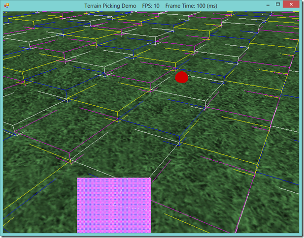
Additionally, we cannot really perform a per-triangle intersection test in any case, since our terrain uses a dynamic LOD system.  The triangles of the terrain mesh are only generated on the GPU, in the hull shader, so we don’t have access to the terrain mesh triangles on the CPU, where we will be doing our picking.  Because of these two constraints, I have decide on using a quadtree of axis-aligned bounding boxes to implement picking on the terrain.  Using a quad tree speeds up our intersection testing considerably, since most of the time we will be able to exclude three-fourths of our terrain from further consideration at each level of the tree.  This also maps quite nicely to the concept of a grid layout for representing our terrain, and allows us to select individual terrain tiles fairly efficiently, since the bounding boxes at the terminal leaves of the tree will thus encompass a single logical terrain tile.  In the screenshot below, you can see how this works; the boxes drawn in color over the terrain are at double the size of the logical terrain tiles, since I ran out of video memory  drawing the terminal bounding boxes, but you can see that the red ball is located on the upper-quadrant of the white bounding box containing it.

bvh


Monday, November 18, 2013 Eric Richards

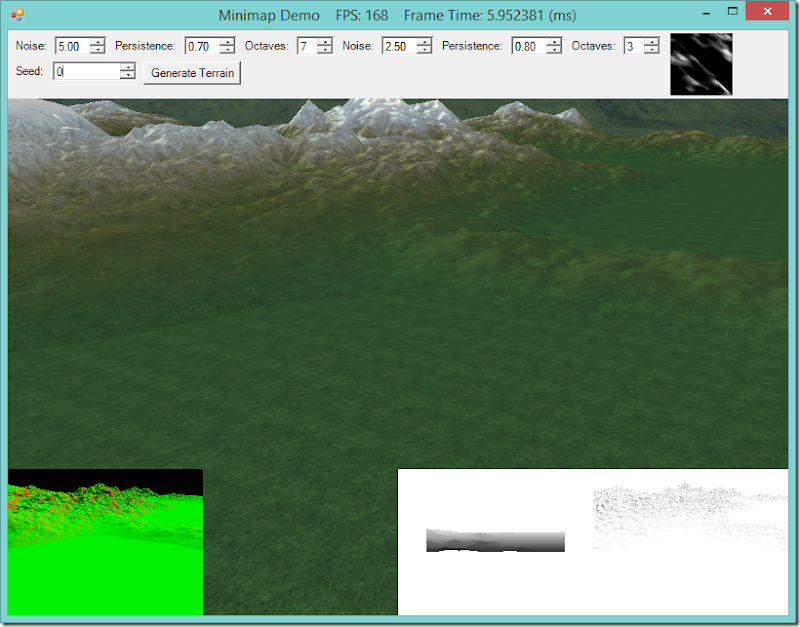
Minimaps are a common feature of many different types of games, especially those in which the game world is larger than the area the player can see on screen at once.  Generally, a minimap allows the player to keep track of where they are in the larger game world, and in many games, particularly strategy and simulation games where the view camera is not tied to any specific player character, allow the player to move their viewing location more quickly than by using the direct camera controls.  Often, a minimap will also provide a high-level view of unit movement, building locations, fog-of-war and other game specific information.

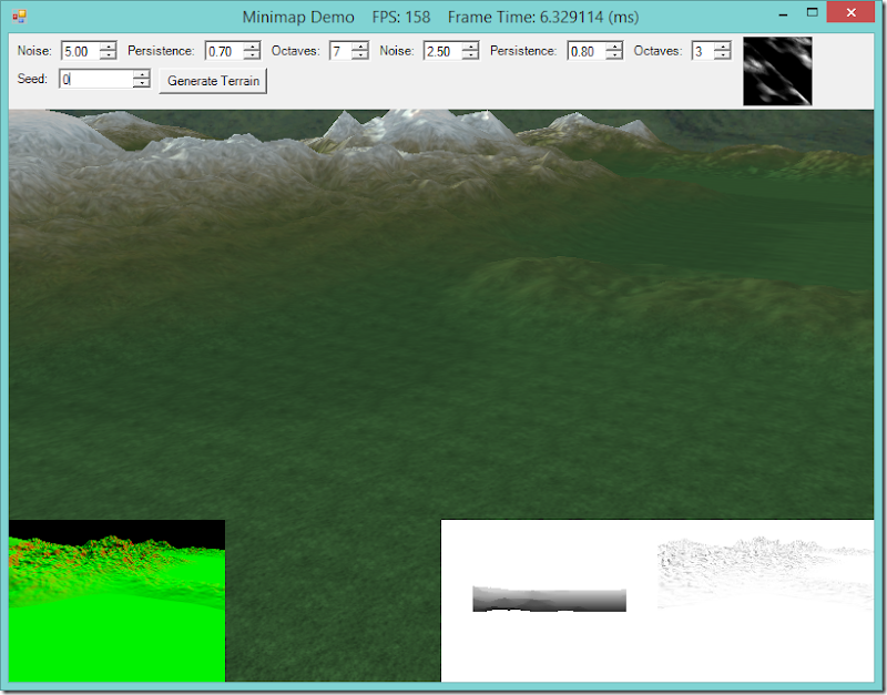
Today, we will look at implementing a minimap that will show us a birds-eye view of the our Terrain class.  We’ll also superimpose the frustum for our main rendering camera over the terrain, so that we can easily see how much of the terrain is in view.  We’ll also support moving our viewpoint by clicking on the minimap.  All of this functionality will be wrapped up into a class, so that we can render multiple minimaps, and place them wherever we like within our application window.

As always, the full code for this example can be downloaded from GitHub, at https://github.com/ericrrichards/dx11.git.  The relevant project is the Minimap project.  The implementation of this minimap code was largely inspired by Chapter 11 of Carl Granberg’s Programming an RTS Game with Direct3D, particularly the camera frustum drawing code.  If you can find a copy (it appears to be out of print, and copies are going for outrageous prices on Amazon…), I would highly recommend grabbing it.

image


Thursday, November 14, 2013 Eric Richards

Now that I’m finished up with everything that I wanted to cover from Frank Luna’s Introduction to 3D Game Programming with Direct3D 11.0 , I want to spend some time improving the Terrain class that we introduced earlier.  My ultimate goal is to create a two tiered strategy game, with a turn-based strategic level and either a turn-based or real-time tactical level.  My favorite games have always been these kinds of strategic/tactical hybrids, such as (in roughly chronological order) Centurion: Defender of Rome, Lords of the Realm, Close Combat and the Total War series.  In all of these games, the tactical combat is one of the main highlights of gameplay, and so the terrain that that combat occurs upon is very important, both aesthetically and for gameplay.

Or first step will be to incorporate some of the graphical improvements that we have recently implemented into our terrain rendering.  We will be adding shadow-mapping and SSAO support to the terrain in this installment.  In the screenshots below, we have our light source (the sun) low on the horizon behind the mountain range.  The first shot shows our current Terrain rendering result, with no shadows or ambient occlusion.  In the second, shadows have been added, which in addition to just showing shadows, has dulled down a lot of the odd-looking highlights in the first shot.  The final shot shows both shadow-mapping and ambient occlusion applied to the terrain.  The ambient occlusion adds a little more detail to the scene; regardless of it’s accuracy, I kind of like the effect, just to noise up the textures applied to the terrain, although I may tweak it a bit to lighten the darker spots up a bit.

We are going to need to add another set of effect techniques to our shader effect, to support shadow mapping, as well as a technique to draw to the shadow map, and another technique to draw the normal/depth map for SSAO.  For the latter two techniques, we will need to implement a new hull shader, since I would like to have the shadow maps and normal-depth maps match the fully-tessellated geometry; using the normal hull shader that dynamically tessellates may result in shadows that change shape as you move around the map.  For the normal/depth technique, we will also need to implement a new pixel shader.  Our domain shader is also going to need to be updated, so that it create the texture coordinates for sampling both the shadow map and the ssao map, and our pixel shader will need to be updated to do the shadow and ambient occlusion calculations.

This sounds like a lot of work, but really, it is mostly a matter of adapting what we have already done.  As always, you can download my full code for this example from GitHub at https://github.com/ericrrichards/dx11.git.  This example doesn’t really have a stand-alone project, as it came about as I was on my way to implementing a minimap, and thus these techniques are showcased as part of the Minimap project.

Basic Terrain Rendering

image

Shadowmapping Added

image

Shadowmapping and SSAO

image


Friday, November 08, 2013 Eric Richards

Quite a while back, I presented an example that rendered water waves by computing a wave equation and updating a polygonal mesh each frame.  This method produced fairly nice graphical results, but it was very CPU-intensive, and relied on updating a vertex buffer every frame, so it had relatively poor performance.

We can use displacement mapping to approximate the wave calculation and modify the geometry all on the GPU, which can be considerably faster.  At a very high level, what we will do is render a polygon grid mesh, using two height/normal maps that we will scroll in different directions and at different rates.  Then, for each vertex that we create using the tessellation stages, we will sample the two heightmaps, and add the sampled offsets to the vertex’s y-coordinate.  Because we are scrolling the heightmaps at different rates, small peaks and valleys will appear and disappear over time, resulting in an effect that looks like waves.  Using different control parameters, we can control this wave effect, and generate either a still, calm surface, like a mountain pond at first light, or big, choppy waves, like the ocean in the midst of a tempest.

This example is based off of the final exercise of Chapter 18 of Frank Luna’s Introduction to 3D Game Programming with Direct3D 11.0 .  The original code that inspired this example is not located with the other example for Chapter 18, but rather in the SelectedCodeSolutions directory.  You can download my source code in full from https://github.com/ericrrichards/dx11.git, under the 29-WavesDemo project.  One thing to note is that you will need to have a DirectX 11 compatible video card to execute this example, as we will be using tessellation stage shaders that are only available in DirectX 11.

image


Sunday, November 03, 2013 Eric Richards

In real-time lighting applications, like games, we usually only calculate direct lighting, i.e. light that originates from a light source and hits an object directly.  The Phong lighting model that we have been using thus far is an example of this; we only calculate the direct diffuse and specular lighting.  We either ignore indirect light (light that has bounced off of other objects in the scene), or approximate it using a fixed ambient term.  This is very fast to calculate, but not terribly physically accurate.  Physically accurate lighting models can model these indirect light bounces, but are typically too computationally expensive to use in a real-time application, which needs to render at least 30 frames per second.  However, using the ambient lighting term to approximate indirect light has some issues, as you can see in the screenshot below.  This depicts our standard skull and columns scene, rendered using only ambient lighting.  Because we are using a fixed ambient color, each object is rendered as a solid color, with no definition.  Essentially, we are making the assumption that indirect light bounces uniformly onto all surfaces of our objects, which is often not physically accurate.

image

Naturally, some portions of our scene will receive more indirect light than other portions, if we were actually modeling the way that light bounces within our scene.  Some portions of the scene will receive the maximum amount of indirect light, while other portions, such as the nooks and crannies of our skull, should appear darker, since fewer indirect light rays should be able to hit those surfaces because the surrounding geometry would, realistically, block those rays from reaching the surface.

In a classical global illumination scheme, we would simulate indirect light by casting rays from the object surface point in a hemispherical pattern, checking for geometry that would prevent light from reaching the point.  Assuming that our models are static, this could be a viable method, provided we performed these calculations off-line; ray tracing is very expensive, since we would need to cast a large number of rays to produce an acceptable result, and performing that many intersection tests can be very expensive.  With animated models, this method very quickly becomes untenable; whenever the models in the scene move, we would need to recalculate the occlusion values, which is simply too slow to do in real-time.

Screen-Space Ambient Occlusion is a fast technique for approximating ambient occlusion, developed by Crytek for the game Crysis.  We will initially draw the scene to a render target, which will contain the normal and depth information for each pixel in the scene.  Then, we can sample this normal/depth surface to calculate occlusion values for each pixel, which we will save to another render target.  Finally, in our usual shader effect, we can sample this occlusion map to modify the ambient term in our lighting calculation.  While this method is not perfectly realistic, it is very fast, and generally produces good results.  As you can see in the screen shot below, using SSAO darkens up the cavities of the skull and around the bases of the columns and spheres, providing some sense of depth.

image

The code for this example is based on Chapter 22 of Frank Luna’s Introduction to 3D Game Programming with Direct3D 11.0 .  The example presented here has been stripped down considerably to demonstrate only the SSAO effects; lighting and texturing have been disabled, and the shadow mapping effects in Luna’s example have been removed.  The full code for this example can be found at my GitHub repository, https://github.com/ericrrichards/dx11.git, under the SSAODemo2 project.  A more faithful adaptation of Luna’s example can also be found in the 28-SsaoDemo project.