Bump and Displacement Mapping with SlimDX and Direct3D 11
Today, we are going to cover a couple of additional techniques that we can use to achieve more realistic lighting in our 3D scenes. Going back to our first discussion of lighting, recall that thus far, we have been using per-pixel, Phong lighting. This style of lighting was an improvement upon the earlier method of Gourad lighting, by interpolating the vertex normals over the resulting surface pixels, and calculating the color of an object per-pixel, rather than per-vertex. Generally, the Phong model gives us good results, but it is limited, in that we can only specify the normals to be interpolated from at the vertices. For objects that should appear smooth, this is sufficient to give realistic-looking lighting; for surfaces that have more uneven textures applied to them, the illusion can break down, since the specular highlights computed from the interpolated normals will not match up with the apparent topology of the surface.
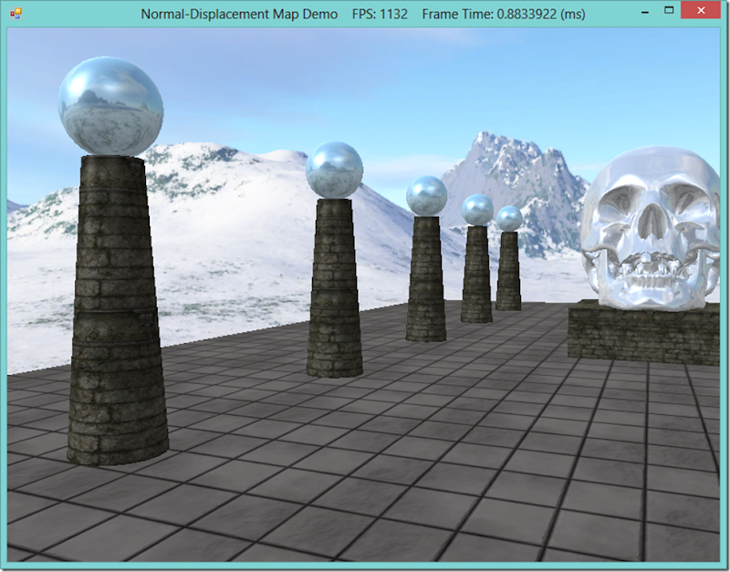
In the screenshot above, you can see that the highlights on the nearest column are very smooth, and match the geometry of the cylinder. However, the column has a texture applied that makes it appear to be constructed out of stone blocks, jointed with mortar. In real life, such a material would have all kinds of nooks and crannies and deformities that would affect the way light hits the surface and create much more irregular highlights than in the image above. Ideally, we would want to model those surface details in our scene, for the greatest realism. This is the motivation for the techniques we are going to discuss today.
One technique to improve the lighting of textured objects is called bump or normal mapping. Instead of just using the interpolated pixel normal, we will combine it with a normal sampled from a special texture, called a normal map, which allows us to match the per-pixel normal to the perceived surface texture, and achieve more believable lighting.
The other technique is called displacement mapping. Similarly, we use an additional texture to specify the per-texel surface details, but this time, rather than a surface normal, the texture, called a displacement map or heightmap, stores an offset that indicates how much the texel sticks out or is sunken in from its base position. We use this offset to modify the position of the vertices of an object along the vertex normal. For best results, we can increase the tessellation of the mesh using a domain shader, so that the vertex resolution of our mesh is as great as the resolution of our heightmap. Displacement mapping is often combined with normal mapping, for the highest level of realism.
This example is based off of Chapter 18 of Frank Luna’s Introduction to 3D Game Programming with Direct3D 11.0 . You can download the full source for this example from my GitHub repository, athttps://github.com/ericrrichards/dx11.git, under the NormalDisplacementMaps project.
NOTE: You will need to have a DirectX 11 compatible video card in order to use the displacement mapping method presented here, as it makes use of the Domain and Hull shaders, which are new to DX 11.
Normal Mapping
For normal mapping, we will use a kind of texture known as a normal map, or sometimes a bump map. Rather than RGB color information, each texel of the normal map will contain a normalized 3D vector. Since we have been using 32-bit textures, we will store the XYZ components of the normal vector in the RGB components of each texel; the alpha component will remain unused for normal mapping (although we could utilize it for some other piece of information, such as the heightmap data that we will use later for displacement mapping). This requires that we compress each floating point component of the normal into an 8-bit integer, usually according to the formula f(x) = (0.5x+0.5) * 255.
Normal map normals are defined in Texture space, where the UV texture axes that we use to sample the texture comprise the X and Y axes. Since most normals will tend to be pointing more or less straight up from the UV texture surface, the normals that we compute will tend to be dominated by the Z component. Because of the way we are compressing the float normal components into 8-bit integers, normal maps tend to be mostly a medium blue color, as you can see in the normal map below:
| Normal map applied to the columns |
Since the normal map normals are defined in texture space, we will need to convert them to world space in order to use them for our lighting. We can do this by creating an appropriate transformation matrix to convert between the texture-space coordinate axes and the world space coordinate axes. Remember that we can specify an orthonormal basis with two vectors, and compute the third by using the cross-product of the other two. The surface normal that we have previously used for lighting comprises one axis of this basis, so now we need an additional basis vector, tangent to the surface.
You may recall that our GeometryGenerator class already computes a tangent vector for each vertex, based on the mathematical formula for the solid. For arbitrary meshes, we need to compute the tangent vector for each face and average these face tangents for each vertex. This will produce an object-space tangent vector, which we can transform into world-space in our vertex shader. Using the cross-product, we can then compute the third component of the per-vertex orthonormal basis, the bitangent, as needed.
After interpolating the vertex normal and tangent for the pixel shader, the interpolated basis may no longer be orthonormal, but we can re-orthonormalize it by subtracting any component of the tangent along the direction of the normal.
We will add a shader function to our LightHelper.fx shader file that will handle this conversion from texture space to world space for us:
//---------------------------------------------------------------------------------------
// Transforms a normal map sample to world space.
//---------------------------------------------------------------------------------------
float3 NormalSampleToWorldSpace(float3 normalMapSample, float3 unitNormalW, float3 tangentW)
{
    // Uncompress each component from [0,1] to [-1,1].
    float3 normalT = 2.0f*normalMapSample - 1.0f;

    // Build orthonormal basis.
    float3 N = unitNormalW;
    float3 T = normalize(tangentW - dot(tangentW, N)*N);
    float3 B = cross(N, T);

    float3x3 TBN = float3x3(T, B, N);

    // Transform from tangent space to world space.
    float3 bumpedNormalW = mul(normalT, TBN);

    return bumpedNormalW;
}
NormalMap Effect
We will create a new shader file for a normal-mapping effect. You can use the Basic.fx shader as a base, as we will only be making a few changes to support normal mapping. First, we need to add a Texture2D for our normal map texture. Next, we need to add tangent coordinates to our vertex structures, and transform the object-space tangent to world-space in our vertex shader. Lastly, we will sample the normal map at each pixel, convert the sampled normal to world space, and use the resulting normal for our lighting calculations. I’ll omit the actual code, as it only differs in about six lines from our Basic.fx, and instead refer you to GitHub for the full source.
Because our NormalMap.fx shader is so similar to our Basic.fx shader, we will actually derive the C# wrapper class for this effect from our BasicEffect wrapper, adding only the necessary effect variables and methods to support the additional normal map texture.
public class NormalMapEffect : BasicEffect {
    private readonly EffectResourceVariable _normalMap;
    public NormalMapEffect(Device device, string filename) : base(device, filename) {
        _normalMap = FX.GetVariableByName("gNormalMap").AsResource();
    }
    public void SetNormalMap(ShaderResourceView tex) {
        _normalMap.SetResource(tex);
    }
}
Vertex Structure
We will need to define a new vertex structure that supports a tangent vector, along with a matching InputLayout.
[StructLayout(LayoutKind.Sequential)]
public struct PosNormalTexTan {
    public Vector3 Pos;
    public Vector3 Normal;
    public Vector2 Tex;
    public Vector3 Tan;
    public static readonly int Stride = Marshal.SizeOf(typeof (PosNormalTexTan));

    public PosNormalTexTan(Vector3 position, Vector3 normal, Vector2 texC, Vector3 tangentU) {
        Pos = position;
        Normal = normal;
        Tex = texC;
        Tan = tangentU;
    }
}

// in InputLayoutDescriptions
public static readonly InputElement[] PosNormalTexTan = {
    new InputElement("POSITION", 0, Format.R32G32B32_Float, 0, 0, InputClassification.PerVertexData, 0),
    new InputElement("NORMAL", 0, Format.R32G32B32_Float, InputElement.AppendAligned, 0, InputClassification.PerVertexData, 0),
    new InputElement("TEXCOORD", 0, Format.R32G32_Float, InputElement.AppendAligned, 0, InputClassification.PerVertexData, 0),
    new InputElement("TANGENT", 0, Format.R32G32B32_Float, InputElement.AppendAligned, 0, InputClassification.PerVertexData,0 )
};

// in InputLayouts.InitAll()
try {
    var passDesc = Effects.NormalMapFX.Light1Tech.GetPassByIndex(0).Description;
    PosNormalTexTan = new InputLayout(device, passDesc.Signature, InputLayoutDescriptions.PosNormalTexTan);
} catch (Exception ex) {
    Console.WriteLine(ex.Message + ex.StackTrace);
    PosNormalTexTan = null;
}
Displacement Mapping
While normal mapping only modified the per-pixel normals of an object’s surface, with displacement mapping, we will actually perturb the geometry of the object’s mesh, to match the apparent nooks and crannies of the surface. To do this, we will use the domain and hull shaders to increase the level of tessellation of the mesh, and offset the new vertices according to a texture called a heightmap. We will actually store this heightmap in the unused alpha channel of our normal map, so that we can utilize both techniques with only a single additional texture.
Because we are going to use tessellation, we need to render our triangles using the primitive topology PrimitiveTopology.PatchListWith3ControlPoints, rather than as a TriangleList. Rendering as a triangle patch allows us to increase the level of tessellation using the hull shader, based on the distance of the object from the camera viewpoint; closer objects will have increased detail, since we will be able to see it more clearly, while farther objects are rendered at a lower level of detail. We control this level of tessellation by setting a minimum and maximum tessellation factor, and distances at which we use the maximum and minimum levels of tessellation, then computing the tessellation factor for each vertex in the vertex shader. The changes to the vertex shader to support this kind of level-of-detail tessellation is as follows:
cbuffer cbPerFrame
{
    float gMaxTessDistance;
    float gMinTessDistance;
    float gMinTessFactor;
    float gMaxTessFactor;
};

struct VertexOut
{
    float3 PosW       : POSITION;
    float3 NormalW    : NORMAL;
    float3 TangentW   : TANGENT;
    float2 Tex        : TEXCOORD;
    float  TessFactor : TESS;
};

VertexOut VS(VertexIn vin)
{
    VertexOut vout;

    // Transform to world space space.
    vout.PosW     = mul(float4(vin.PosL, 1.0f), gWorld).xyz;
    vout.NormalW  = mul(vin.NormalL, (float3x3)gWorldInvTranspose);
    vout.TangentW = mul(vin.TangentL, (float3x3)gWorld);

    // Output vertex attributes for interpolation across triangle.
    vout.Tex = mul(float4(vin.Tex, 0.0f, 1.0f), gTexTransform).xy;

    float d = distance(vout.PosW, gEyePosW);

    // Normalized tessellation factor.
    // The tessellation is
    //   0 if d >= gMinTessDistance and
    //   1 if d <= gMaxTessDistance.
    float tess = saturate( (gMinTessDistance - d) / (gMinTessDistance - gMaxTessDistance) );

    // Rescale [0,1] --> [gMinTessFactor, gMaxTessFactor].
    vout.TessFactor = gMinTessFactor + tess*(gMaxTessFactor-gMinTessFactor);

    return vout;
}
Hull Shader
The primary job of our hull shader is to select the interior and exterior tessellation factors that will instruct the GPU how to tessellate the triangle patch. We do this by averaging the tessellation factor for the two vertices in each edge for the exterior patch tessellation factors, and select a matching factor for the interior factor.
struct PatchTess
{
    float EdgeTess[3] : SV_TessFactor;
    float InsideTess  : SV_InsideTessFactor;
};

PatchTess PatchHS(InputPatch<VertexOut,3> patch,
                  uint patchID : SV_PrimitiveID)
{
    PatchTess pt;

    // Average tess factors along edges, and pick an edge tess factor for
    // the interior tessellation.  It is important to do the tess factor
    // calculation based on the edge properties so that edges shared by
    // more than one triangle will have the same tessellation factor.
    // Otherwise, gaps can appear.
    pt.EdgeTess[0] = 0.5f*(patch[1].TessFactor + patch[2].TessFactor);
    pt.EdgeTess[1] = 0.5f*(patch[2].TessFactor + patch[0].TessFactor);
    pt.EdgeTess[2] = 0.5f*(patch[0].TessFactor + patch[1].TessFactor);
    pt.InsideTess  = pt.EdgeTess[0];

    return pt;
}

struct HullOut
{
    float3 PosW     : POSITION;
    float3 NormalW  : NORMAL;
    float3 TangentW : TANGENT;
    float2 Tex      : TEXCOORD;
};

[domain("tri")]
[partitioning("fractional_odd")]
[outputtopology("triangle_cw")]
[outputcontrolpoints(3)]
[patchconstantfunc("PatchHS")]
HullOut HS(InputPatch<VertexOut,3> p,
           uint i : SV_OutputControlPointID,
           uint patchId : SV_PrimitiveID)
{
    HullOut hout;

    // Pass through shader.
    hout.PosW     = p[i].PosW;
    hout.NormalW  = p[i].NormalW;
    hout.TangentW = p[i].TangentW;
    hout.Tex      = p[i].Tex;

    return hout;
}
Domain Shader
The domain shader is invoked for each vertex created by the hull shader and tessellation stage. The inputs to this shader are the barycentric coordinates of the generated vertex, relative to the input patch, along with the control points of the patch. We interpolate the position, normal, tangent and texture coordinates of the new vertex from the control points and the barycentric coordinate. Next, we sample the heightmap, stored in the alpha channel of the normal map, and displace the position of the vertex along the normal vector. Finally, we transform the vertex position to clip space using the view-projection matrix. One thing to note is that we need to select the mipmap level of the texture to sample ourselves.
struct DomainOut
{
    float4 PosH     : SV_POSITION;
    float3 PosW     : POSITION;
    float3 NormalW  : NORMAL;
    float3 TangentW : TANGENT;
    float2 Tex      : TEXCOORD;
};

// The domain shader is called for every vertex created by the tessellator.
// It is like the vertex shader after tessellation.
[domain("tri")]
DomainOut DS(PatchTess patchTess,
             float3 bary : SV_DomainLocation,
             const OutputPatch<HullOut,3> tri)
{
    DomainOut dout;

    // Interpolate patch attributes to generated vertices.
    dout.PosW     = bary.x*tri[0].PosW     + bary.y*tri[1].PosW     + bary.z*tri[2].PosW;
    dout.NormalW  = bary.x*tri[0].NormalW  + bary.y*tri[1].NormalW  + bary.z*tri[2].NormalW;
    dout.TangentW = bary.x*tri[0].TangentW + bary.y*tri[1].TangentW + bary.z*tri[2].TangentW;
    dout.Tex      = bary.x*tri[0].Tex      + bary.y*tri[1].Tex      + bary.z*tri[2].Tex;

    // Interpolating normal can unnormalize it, so normalize it.
    dout.NormalW = normalize(dout.NormalW);

    //
    // Displacement mapping.
    //

    // Choose the mipmap level based on distance to the eye; specifically, choose
    // the next miplevel every MipInterval units, and clamp the miplevel in [0,6].
    const float MipInterval = 20.0f;
    float mipLevel = clamp( (distance(dout.PosW, gEyePosW) - MipInterval) / MipInterval, 0.0f, 6.0f);

    // Sample height map (stored in alpha channel).
    float h = gNormalMap.SampleLevel(samLinear, dout.Tex, mipLevel).a;

    // Offset vertex along normal.
    dout.PosW += (gHeightScale*(h-1.0))*dout.NormalW;

    // Project to homogeneous clip space.
    dout.PosH = mul(float4(dout.PosW, 1.0f), gViewProj);

    return dout;
}
Pixel Shader
You may notice that the DomainOut structure is the same as the VertexOut structure we have used for our normal mapping pixel shader. In fact, the pixel shader for our displacement mapping effect is exactly the same as in the previous technique.
C# Effect Wrapper Class: DisplacementMapEffect
Because of the similarities between the displacement mapping effect and the previous normal mapping effect, we can subclass our NormalMapEffect wrapper class as a basis for our DisplacementMapEffect. We need only add the necessary effect variable handles to access the additional shader constants and functions to set their values.
public class DisplacementMapEffect : NormalMapEffect {
    private readonly EffectScalarVariable _heightScale;
    private readonly EffectScalarVariable _maxTessDistance;
    private readonly EffectScalarVariable _minTessDistance;
    private readonly EffectScalarVariable _minTessFactor;
    private readonly EffectScalarVariable _maxTessFactor;
    private readonly EffectMatrixVariable _viewProj;

    public DisplacementMapEffect(Device device, string filename) : base(device, filename) {
        _heightScale = FX.GetVariableByName("gHeightScale").AsScalar();
        _maxTessDistance = FX.GetVariableByName("gMaxTessDistance").AsScalar();
        _minTessDistance = FX.GetVariableByName("gMinTessDistance").AsScalar();
        _minTessFactor = FX.GetVariableByName("gMinTessFactor").AsScalar();
        _maxTessFactor = FX.GetVariableByName("gMaxTessFactor").AsScalar();
        _viewProj = FX.GetVariableByName("gViewProj").AsMatrix();
    }

    public void SetHeightScale(float f) {
        _heightScale.Set(f);
    }

    public void SetMaxTessDistance(float f) {
        _maxTessDistance.Set(f);
    }

    public void SetMinTessDistance(float f) {
        _minTessDistance.Set(f);
    }

    public void SetMinTessFactor(float f) {
        _minTessFactor.Set(f);
    }

    public void SetMaxTessFactor(float f) {
        _maxTessFactor.Set(f);
    }

    public void SetViewProj(Matrix viewProj) {
        _viewProj.SetMatrix(viewProj);
    }
}
The Demo
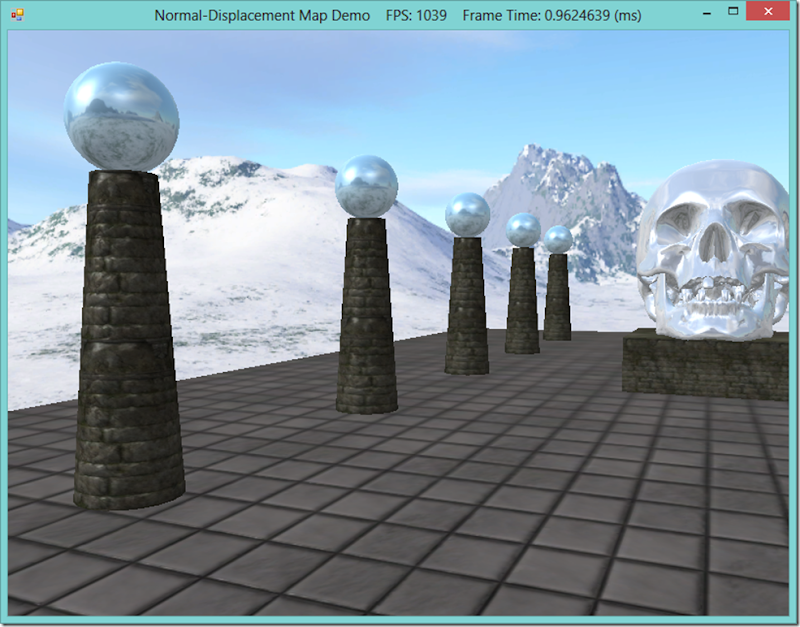
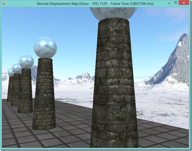
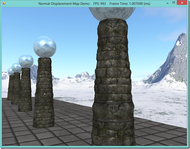
As the only complexity involved in the demo application arises from the feature that allows the user to switch between the basic, normal mapping, and displacement mapping effects, I will forgo discussing the implementation; you may peruse the full source on GitHub. Instead, we’ll close by comparing the three rendering methods side-by-side.
| Basic rendering |
 |
| Normal Mapped |
 |
| Displacement Mapped |
 |
Next Time
The next section in the book is on rendering a terrain, using heightmaps, texture splatting and a level-of-detail effect similar to the one we used here for displacement mapping. I may bounce back to Chapter 13 instead, and brush up on the Hull Shader and Domain Shader, since I am realizing that skipping them was an oversight; the hull and domain shaders are relatively complex, and I can’t do them full justice in the midst of explaining another concept.


