Camera Picking in SlimDX and Direct3D 11
So far, we have only been concerned with drawing a 3D scene to the 2D computer screen, by projecting the 3D positions of objects to the 2D pixels of the screen. Often, you will want to perform the reverse operation; given a pixel on the screen, which object in the 3D scene corresponds to that pixel? Probably the most common application for this kind of transformation is selecting and moving objects in the scene using the mouse, as in most modern real-time strategy games, although the concept has other applications.
The traditional method of performing this kind of object picking relies on a technique called ray-casting. We shoot a ray from the camera position through the selected point on the near-plane of our view frustum, which is obtained by converting the screen pixel location into normalized device coordinates, and then intersect the resulting ray with each object in our scene. The first object intersected by the ray is the object that is “picked.”
The code for this example is based on Chapter 16 of Frank Luna’s Introduction to 3D Game Programming with Direct3D 11.0 , with some modifications. You can download the full source from my GitHub repository at https://github.com/ericrrichards/dx11.git, under the PickingDemo project.
Picking Rays
Mathematically, a ray starts at a given point, and extends in a direction until infinity. Normally, we model this by using an origin coordinate and a direction vector. We will be using the SlimDX Ray class, which provides these position and direction properties, as well as intersection tests for bounding boxes, spheres, triangles and planes.
To pick an object, we need to convert the selected screen pixel into the camera’s view space, create a ray from the camera’s position towards the view-space position, then transform the ray in view space into world space. We can convert a screen-space coordinate to view space by first converting the pixel position to normalized device coordinates, then unprojecting the device coordinate into view space using the camera’s projection matrix. Normalized device coordinates map the screen x and y coordinates into the range [-1, 1]. We create the view-space picking ray by creating a ray with its origin at [0,0,0] (the camera’s view-space origin), and use the transformed screen-space coordinates as the ray’s direction. Next, we transform the ray into world space, by transforming the origin and direction vectors of the ray by the inverse of the camera’s view matrix. Lastly, we normalize the ray’s direction vector.
public Ray GetPickingRay(Vector2 sp, Vector2 screenDims) {
    var p = Proj;
    // convert screen pixel to view space
    var vx = (2.0f * sp.X / screenDims.X - 1.0f) / p.M11;
    var vy = (-2.0f * sp.Y / screenDims.Y + 1.0f) / p.M22;

    var ray = new Ray(new Vector3(), new Vector3(vx, vy, 1.0f));
    var v = View;
    var invView = Matrix.Invert(v);


    var toWorld = invView;

    ray = new Ray(Vector3.TransformCoordinate(ray.Position, toWorld), Vector3.TransformNormal(ray.Direction, toWorld));

    ray.Direction.Normalize();
    return ray;
}
I have added this method to our CameraBase class, so that we can generate a picking ray for both of our camera types.
Picking an Object in the 3D Scene
We’ll be using a right mouse button click to select a triangle from our car mesh in this example. This changes our OnMouseDown override slightly:
protected override void OnMouseDown(object sender, MouseEventArgs mouseEventArgs) {
    if (mouseEventArgs.Button == MouseButtons.Left) {
        _lastMousePos = mouseEventArgs.Location;
        Window.Capture = true;
    } else if (mouseEventArgs.Button == MouseButtons.Right) {
        Pick(mouseEventArgs.X, mouseEventArgs.Y);
    }
}
Our Pick() method will perform the actual triangle picking from our car mesh. Out first step is to get the camera picking ray from the mouse coordinates that we have passed in to the function. Next, to simplify the collision tests with our car mesh, we will transform the picking ray into the local object space of the mesh by using the inverse of the mesh’s world matrix. Since our model consists of a large number of triangles, we perform a ray-bounding box intersection test first; if the ray does not intersect the bounding box, we can safely skip the more expensive per-triangle intersection test. Next, we iterate through the triangles of the mesh, using an in-memory copy of the car’s index and vertex buffers. We have to be sure that we select the nearest triangle to the camera, as we may have multiple triangles at different depths projected to the same screen point. We save the first index of the picked triangle, so that we can draw that triangle in a different color than the rest of the mesh.
private void Pick(int sx, int sy ) {

    var ray = _cam.GetPickingRay(new Vector2(sx, sy), new Vector2(ClientWidth, ClientHeight) );

    // transform the picking ray into the object space of the mesh
    var invWorld = Matrix.Invert(_meshWorld);
    ray.Direction = Vector3.TransformNormal(ray.Direction, invWorld);
    ray.Position = Vector3.TransformCoordinate(ray.Position, invWorld);
    ray.Direction.Normalize();

    _pickedTriangle = -1;
    float tmin;
    if (!Ray.Intersects(ray, _meshBox, out tmin)) return;

    tmin = float.MaxValue;
    for (var i = 0; i < _meshIndices.Count/3; i++) {
        var v0 = _meshVertices[_meshIndices[i * 3]].Position;
        var v1 = _meshVertices[_meshIndices[i * 3 + 1]].Position;
        var v2 = _meshVertices[_meshIndices[i * 3 + 2]].Position;

        float t;

        if (!Ray.Intersects(ray, v0, v1, v2, out t)) continue;
        // find the closest intersection, exclude intersections behind camera
        if (!(t < tmin || t < 0)) continue;
        tmin = t;
        _pickedTriangle = i;
    }
}
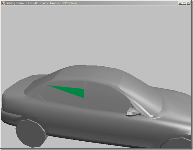
Once we have determined which triangle the user has selected, the only thing remaining is to draw the mesh, using a different material for the selected triangle. We do this by rendering the mesh normally, and then we draw the picked triangle again, using the new material. We have to change the DepthStencil state in order to do this, as otherwise, the repeated triangle would fail the depth test. So, we have created a new DepthStencilState object, which changes the default depth test (<, Less than), to a <= (less than or equal) operation. This will allow the repeated triangle to be drawn.
public override void DrawScene() {
   // clear the render target, set topology and inputLayout,
   // set shader variables

    for (int p = 0; p < activeTech.Description.PassCount; p++) {
        if (Util.IsKeyDown(Keys.D1)) {  // draw wireframe
            ImmediateContext.Rasterizer.State = RenderStates.WireframeRS;
        }
        // draw mesh normally...
        if (_pickedTriangle >= 0) {
            ImmediateContext.OutputMerger.DepthStencilState = RenderStates.LessEqualDSS;
            ImmediateContext.OutputMerger.DepthStencilReference = 0;

            Effects.BasicFX.SetMaterial(_pickedTriangleMat);
            pass.Apply(ImmediateContext);
            ImmediateContext.DrawIndexed(3, 3*_pickedTriangle, 0);

            ImmediateContext.OutputMerger.DepthStencilState = null;
        }

    }
    SwapChain.Present(0, PresentFlags.None);
}
Creating this new DepthStencilState is quite straightforward. From our RenderStates.InitAll() function:
var lessEqualDesc = new DepthStencilStateDescription {
    IsDepthEnabled = true,
    DepthWriteMask = DepthWriteMask.All,
    DepthComparison = Comparison.LessEqual,
    IsStencilEnabled = false
};
LessEqualDSS = DepthStencilState.FromDescription(device, lessEqualDesc);
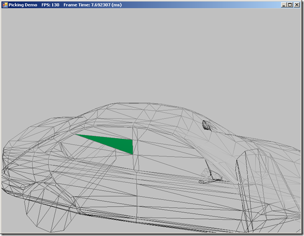
You may have also noticed that we provide the option to draw the mesh in wire-frame mode, with the selected triangle drawn solid. This can help more easily visualize which triangle is selected.
Next Time…
Next up on our plate is Chapter 17, Cube Mapping. We’ll cover a special kind of texture called a cube map, and look at how we can use cube maps to render reflections on arbitrary objects, and sky and distant backgrounds.


