
Geodesic Sphere Tessellation
A couple of weeks ago as I was browsing HackerNews, I stumbled onto an article about creating spherical procedural maps by Andy Gainey. Procedural terrain/map generation is always something I find interesting, having grown up slightly obsessed with Civilization and its successors. Various methods of tiling a sphere in order to make a game grid have been bouncing around the back of my mind for a while now - unfortunately finding time to explore some of those ideas has been problematic. But, after reading through Mr. Gainey's piece and looking over the source for his demo, I got inspired to take a stab at something similar. My first attempt was to try to directly port his Javascript implementation, which got bogged down in the impedance mismatch between going from JS to C# and WebGL to DirectX at the same time, so I stepped back, and decided to come at the idea again, working in smaller steps.
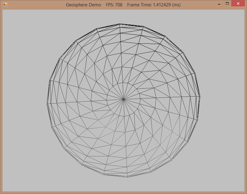
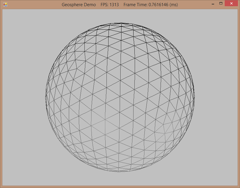
The first step was to generate a spherical triangle mesh. For this purpose, the spherical mesh that we have previously worked with is not very well suited, as its topology is very inconsistent, particularly around the poles, as you can see in the screenshot below. Instead of this kind of lattitude/longitude subdivision, we will instead use an alternate method, which starts from an icosahedron, then subdivides each face of the icosahedron into four triangles, and finally projects the resulting vertices onto the sphere. This produces a much more regular tessellation, known as a geodesic grid, as you can see in the right screenshot below. This tessellation is not without artifacts - at the vertices of the original icosahedron, the resulting geodesic will have five edges, while all other vertices have six edges, similar to a real-life soccer ball.
Frank Luna's Introduction to 3D Game Programming with Direct3D 11.0, Chapter 6, presented a method of generating of generating a geodesic sphere, which I previously skipped over. The code for this example is based upon his example, with some improvements to eliminate redundant vertices.
The code for this example can be obtained from my GitHub repository.
Generating the Icosahedron
We're going to store the vertex positions and indices for the icosahedron which circumscribes a sphere of radius 1 in static readonly fields of our GeometryGenerator class, so that we will only have one copy of the base geometry. This is taken verbatim from Luna's source - I have been looking fruitlesly for a clear, concise derivation of the calculation of these vertex positions, but have yet to come up with anything I can really wrap my head around. The best explanation seems to be David Eberly's but this doesn't seem to match up exactly with either Luna's or Gainey's implementation, so if you know of a better explanation please reply in the comments section.
private static readonly List<Vector3> IcosahedronVertices = new List<Vector3> {
    new Vector3(-0.525731f, 0, 0.850651f), new Vector3(0.525731f, 0, 0.850651f),
    new Vector3(-0.525731f, 0, -0.850651f), new Vector3(0.525731f, 0, -0.850651f),
    new Vector3(0, 0.850651f, 0.525731f), new Vector3(0, 0.850651f, -0.525731f),
    new Vector3(0, -0.850651f, 0.525731f), new Vector3(0, -0.850651f, -0.525731f),
    new Vector3(0.850651f, 0.525731f, 0), new Vector3(-0.850651f, 0.525731f, 0),
    new Vector3(0.850651f, -0.525731f, 0), new Vector3(-0.850651f, -0.525731f, 0)
};
private static readonly List<int> IcosahedronIndices = new List<int> {
    1,4,0,  4,9,0,  4,5,9,  8,5,4,  1,8,4,
    1,10,8, 10,3,8, 8,3,5,  3,2,5,  3,7,2,
    3,10,7, 10,6,7, 6,11,7, 6,0,11, 6,1,0,
    10,1,6, 11,0,9, 2,11,9, 5,2,9,  11,2,7
};
Creating the Geosphere
We will generate the geodesic sphere by taking the unit icosahedron geometry, subdividing its faces zero or more times, then projecting the resulting vertices to the unit sphere, then scaling these projected vertices to the desired radius. We will also generate texture coordinates and the tangent vector, by using spherical coordinates.
NOTE: To support higher subdivision levels, I had to bump my model classes up from 16-bit to 32-bit index buffer formats - Format.R32_UInt vs Format.R16_UInt
NOTE: In my experimentation, I'm only able to support up to eight subdivisions before resulting in some cryptic DirectX errors. I think this is due to VRAM memory limits on my graphics card. I'm also running up against some .NET memory limit issues. It may be necessary to offload calculation of some of the vertex elements calculated here to the vertex shader on the GPU as I continue with this.
GeometryGenerator.cs
public enum SubdivisionCount {
    None = 0,
    One = 1,
    Two = 2,
    Three = 3,
    Four = 4,
    Five = 5,
    Six = 6,
    Seven = 7,
    Eight = 8
}
public static MeshData CreateGeosphere(float radius, SubdivisionCount numSubdivisions) {
    var tempMesh = new MeshData();
    tempMesh.Vertices = IcosahedronVertices.Select(p => new Vertex { Position = p }).ToList();
    tempMesh.Indices = IcosahedronIndices;
    var mh = new Subdivider();
    for (var i = 0; i < (int)numSubdivisions; i++) {
        mh.Subdivide4(tempMesh);
    }
    // Project vertices onto sphere and scale.
    for (var i = 0; i < tempMesh.Vertices.Count; i++) {
    // Project onto unit sphere.
        var n = Vector3.Normalize(tempMesh.Vertices[i].Position);
        var p = radius * n;
    // Derive texture coordinates from spherical coordinates.
        var theta = MathF.AngleFromXY(tempMesh.Vertices[i].Position.X, tempMesh.Vertices[i].Position.Z);
        var phi = MathF.Acos(tempMesh.Vertices[i].Position.Y / radius);
        var texC = new Vector2(theta / (2 * MathF.PI), phi / MathF.PI);
    // Partial derivative of P with respect to theta
        var tangent = new Vector3(
            -radius * MathF.Sin(phi) * MathF.Sin(theta),
            0,
            radius * MathF.Sin(phi) * MathF.Cos(theta)
        );
        tangent.Normalize();
        tempMesh.Vertices[i] = new Vertex(p, n, tangent, texC);
    }
    return tempMesh;
}
MathF.cs
public static float AngleFromXY(float x, float y) {
    float theta;
    if (x >= 0.0f) {
        theta = Atan(y/x);
    if (theta < 0.0f) {
            theta += 2*PI;
        }
    } else {
        theta = Atan(y/x) + PI;
    }
    return theta;
}
Subdividing the Icosahedron
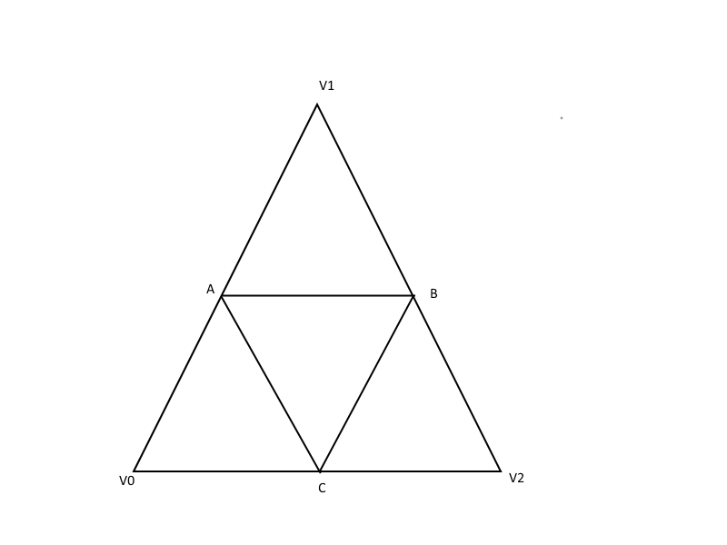
When we subdivide the triangles of the icosahedron, we will break the original triangle into 4 new triangles, by creating new vertices at the midpoints of the edges between the original vertices. The diagram below shows this subdivision, with the original vertices (V0, V1, V2) and the new midpoint vertices (A,B,C).
The original code by Luna is somewhat naive, as it does not check whether any of the vertices generated by subdividing the triangle are shared by other triangles which have already been subdivided. This results in a large number of duplicated vertices, which is wasteful of vertex buffer memory - up to 2 copies of the mid-point vertices can be duplicated and up to 6 copies of the original vertices, and this is acacerbated at higher subdivision levels, as the cumulative effect of duplication at lower subdivision levels grows. By caching the index of each processed vertex, we can avoid this duplication and acheive the ideal minimum number of vertices in the subdivided mesh.
This is achieved by adapting the technique illustrated here (more generalized version available here). The algorithm, in broad strokes is:
- Create a new index buffer.
- Create a dictionary containing the indices of any new bisecting vertices in the vertex buffer, indexed by a tuple consisting of the indices of the two vertices whose edge the new vertex bisects in the vertex buffer.
-
For each triangle in the original mesh:
- For the three bisecting vertices, check the dictionary to see if we have already created the new vertex. Note that we have to check the edge (v, v') and the edge (v', v) since the new vertex may have been created in either order.
- If the bisecting vertex has already been created, return the index in the vertex buffer stored in the dictionary.
- If the bisecting vertex does not exist, create the bisecting vertex, add it to the vertex buffer, and store the resulting index in the dictionary
- Add the indices for each of the four new triangles to the new index buffer.
- Replace the original index buffer with the new index buffer.
private class Subdivider {
    private List<Vertex> _vertices;
    private List<int> _indices;
    private Dictionary<Tuple<int, int>, int> _newVertices;
    public void Subdivide4(MeshData mesh) {
        _newVertices = new Dictionary<Tuple<int, int>, int>();
        _vertices = mesh.Vertices;
        _indices = new List<int>();
        var numTris = mesh.Indices.Count / 3;
    for (var i = 0; i < numTris; i++) {
    //       i2
    //       *
    //      / \
    //     /   \
    //   a*-----*b
    //   / \   / \
    //  /   \ /   \
    // *-----*-----*
    // i1    c      i3
            var i1 = mesh.Indices[i * 3];
            var i2 = mesh.Indices[i * 3 + 1];
            var i3 = mesh.Indices[i * 3 + 2];
            var a = GetNewVertex(i1, i2);
            var b = GetNewVertex(i2, i3);
            var c = GetNewVertex(i3, i1);
            _indices.AddRange(new[] {
                i1, a, c,
                i2, b, a,
                i3, c, b,
                a, b, c
            });
        }
#if DEBUG
        Console.WriteLine(mesh.Vertices.Count);
#endif
        mesh.Indices = _indices;
    }
    private int GetNewVertex(int i1, int i2) {
        var t1 = new Tuple<int, int>(i1, i2);
        var t2 = new Tuple<int, int>(i2, i1);
    if (_newVertices.ContainsKey(t2)) {
    return _newVertices[t2];
        }
    if (_newVertices.ContainsKey(t1)) {
    return _newVertices[t1];
        }
        var newIndex = _vertices.Count;
        _newVertices.Add(t1, newIndex);
        _vertices.Add(new Vertex() { Position = (_vertices[i1].Position + _vertices[i2].Position) * 0.5f });
    return newIndex;
    }
}
Model Class Factory Method
To integrate this new funtionality into our existing model class, we'll create a new factory method on the IModel class to call the CreateGeosphere function and initialize a Model object with the resulting geometry. Below is the implementation from the BasicModel class:
public override void CreateGeosphere(Device device, float radius, GeometryGenerator.SubdivisionCount numSubdivisions) {
    var geosphere = GeometryGenerator.CreateGeosphere(radius, numSubdivisions);
    InitFromMeshData(device, geosphere);
}
The usage of this method looks like this:
_geosphereModel = new BasicModel();
_geosphereModel.CreateGeosphere(Device, 5, GeometryGenerator.SubdivisionCount.Three);
Results:
We'll dispense with discussing the example program in any depth - if you are interested, you can download the project and play with it yourself. The 0-8 keys will regenerate the geodesic sphere mesh with the corresponding number of subdivisions. The W key can be used to view the mesh as a wireframe, to show the tessellation at different levels. You can also switch between viewing the geodesic (G) and lat/long sphere (S) tessellations.

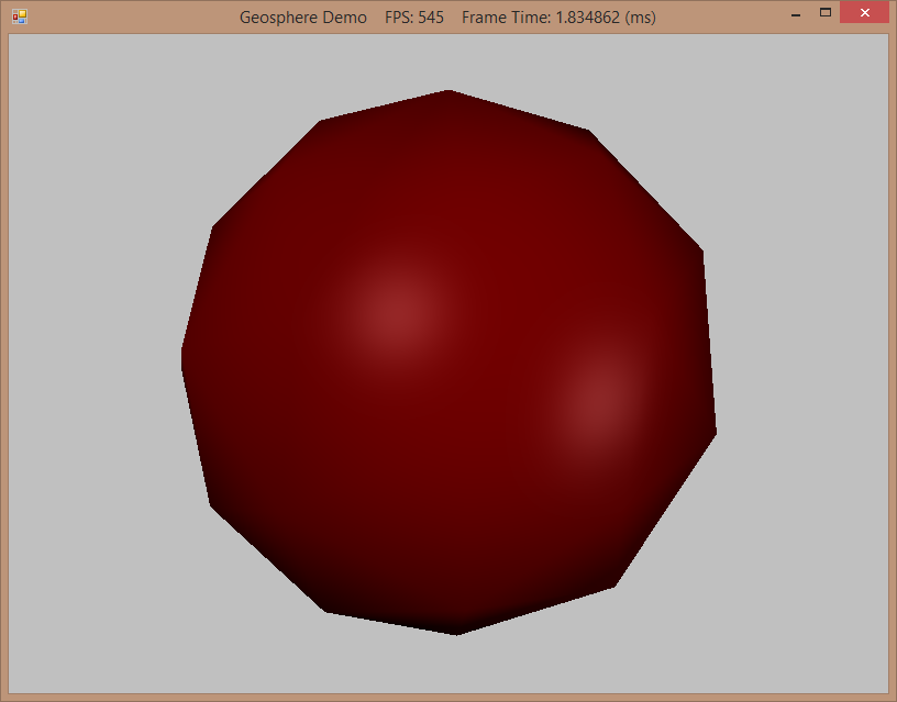

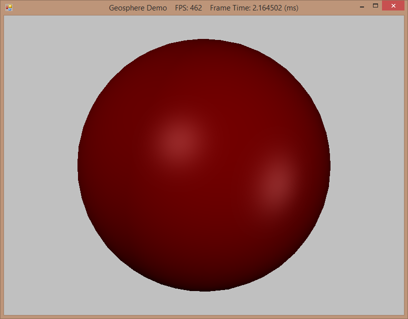
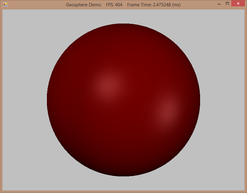
After 4 subdivisions, there is no appreciable increase in visual quality.
Next Time...
Hopefully, it won't take me another month to come up with something to post. I keep saying that...
I still need to write up my work on Voronoi mapping, and there is always more to do from the HLSL Cookbook. I may also go further down the path of generating a spherical game map, if I can get some time to figure out how to convert this geosphere into a hexagonal tiling, or something more like the irregular tiling used by Andy Gainey. We'll see.